Electrical Engineering > Lab Report > Fundamentals of Electronic Circuits Manual ACTIVITY 2: Diode Characteristics (All)
Fundamentals of Electronic Circuits Manual ACTIVITY 2: Diode Characteristics
Document Content and Description Below
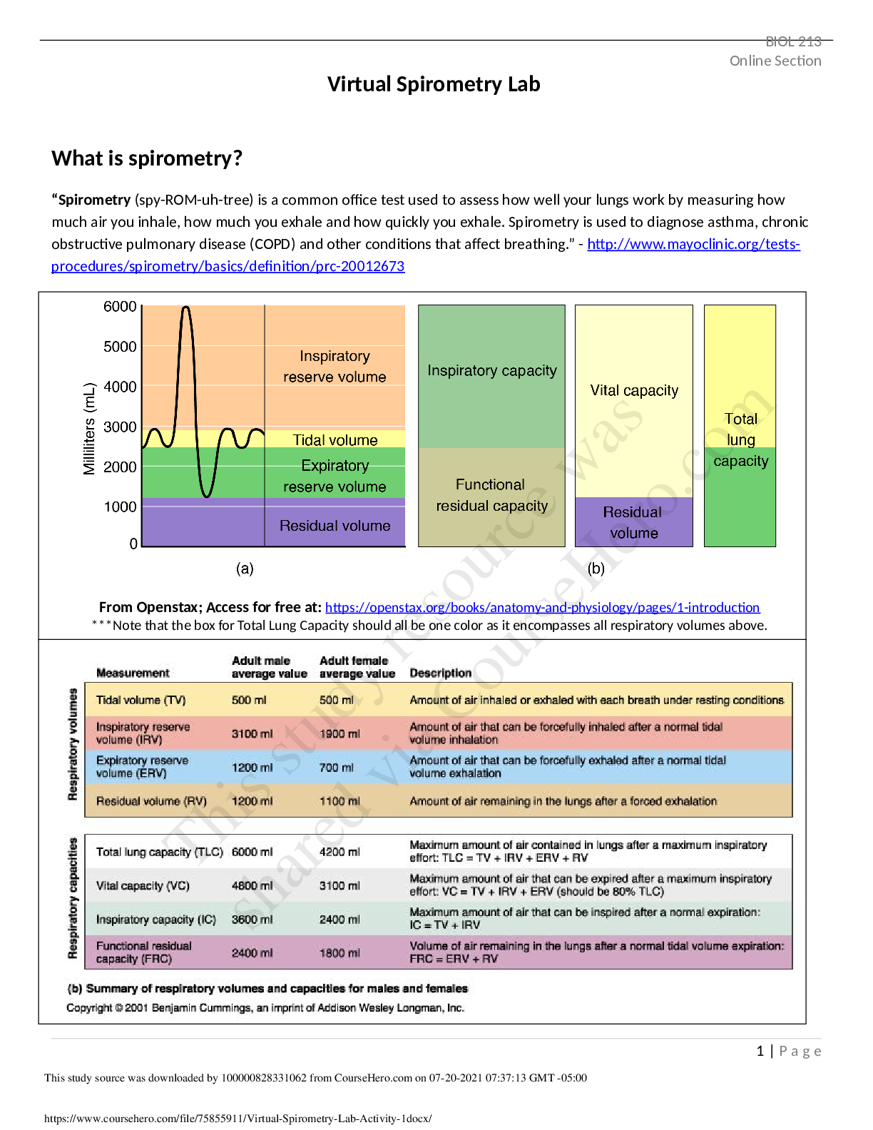
ELECTRICAL AND ELECTRONICS ENGINEERING DEPARTMENT Fundamentals of Electronic Circuits Manual ACTIVITY 2: Diode Characteristics 2.1 Program Outcomes (POs) Addressed by the Activity a. ability to a... pply knowledge of mathematics and science to solve engineering problems b. ability to design and conduct fieldworks, as well as to analyze and interpret data c. ability to function on multidisciplinary teams 2.2 Activity’s Intended Learning Outcomes (AILOs) At the end of this activity, the student shall be able to: a. identify the diode’s threshold voltage b. calculate the diode’s AC and DC resistances c. evaluate the precision of the experiment conducted 2.3 Objectives of the Activity The objective of this activity is to: a. be familiar with the characteristics of a silicon diode 2.4 Principle of the Activity Most modern day digital multimeters can be used to determine the condition of a diode. They have a scale denoted by a diode symbol that will indicate the condition of a diode in the forward- and reverse-bias regions. If connected to establish a forward-bias condition, the meter will display the forward voltage across the diode at a current level typically in the neighbourhood of 2 mA. If connected to establish a reverse-bias condition, an “OL” should appear on the display to support the open-circuit approximation frequently applied to this region. If the meter does not have diode-checking capability the condition of the diode can also be checked by obtaining some measure of the resistance level in the forward and reverse-bias regions. Both techniques for checking diode will be introduced in the first part of the experiment. The characteristics of a silicon or germanium diode have the general shape shown in Fig. 2.1. Note the change in scale for both the vertical and horizontal axes. In the reverse-biased region, the reverse saturation currents are fairly constant from 0V to the zener potential. In the forward-bias region the current increases quite rapidly with increasing diode voltage. Note that the curve is rising almost vertically at a forward-biased voltage of less than 1V. The forwardACTIVITY 2: DIODE CHARACTERISTICS 1biased diode current will be limited solely by the network in which the diode is connected or by the maximum current or power rating of the diode. The “firing potential” or threshold voltage is determined by extending a straight line (dashed lines of Fig. 2.1) tangent to the curves until it hits the horizontal axis. The intersection with the VD axis will determine the threshold voltage VT. The DC or static resistance of a diode at any point on the characteristics is determined by the ratio of the diode voltage at any point, divided by the diode current [Show More]
Last updated: 1 year ago
Preview 1 out of 16 pages

Reviews( 0 )
Document information
Connected school, study & course
About the document
Uploaded On
May 20, 2021
Number of pages
16
Written in

Additional information
This document has been written for:
Uploaded
May 20, 2021
Downloads
0
Views
144
.png)


.png)
.png)


 (1).png)