Electronics > EXAM > ECET220 Week 3 Lab–Op-Amps questions and answers solution 2020 full solved problem docs DeVry Univ (All)
ECET220 Week 3 Lab–Op-Amps questions and answers solution 2020 full solved problem docs DeVry University
Document Content and Description Below
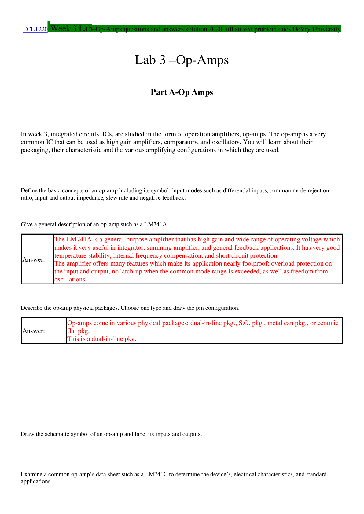
ECET220 Week 3 Lab–Op-Amps questions and answers solution 2020 full solved problem docs DeVry University Lab 3 –Op-Amps Part A-Op Amps In week 3, integrated circuits, ICs, are studied... in the form of operation amplifiers, op-amps. The op-amp is a very common IC that can be used as high gain amplifiers, comparators, and oscillators. You will learn about their packaging, their characteristic and the various amplifying configurations in which they are used. Define the basic concepts of an op-amp including its symbol, input modes such as differential inputs, common mode rejection ratio, input and output impedance, slew rate and negative feedback. Give a general description of an op-amp such as a LM741A. Answer: The LM741A is a general-purpose amplifier that has high gain and wide range of operating voltage which makes it very useful in integrator, summing amplifier, and general feedback applications. It has very good temperature stability, internal frequency compensation, and short circuit protection. The amplifier offers many features which make its application nearly foolproof: overload protection on the input and output, no latch-up when the common mode range is exceeded, as well as freedom from oscillations. Describe the op-amp physical packages. Choose one type and draw the pin configuration. Answer: Op-amps come in various physical packages: dual-in-line pkg., S.O. pkg., metal can pkg., or ceramic flat pkg. This is a dual-in-line pkg. Draw the schematic symbol of an op-amp and label its inputs and outputs. Examine a common op-amp’s data sheet such as a LM741C to determine the device’s, electrical characteristics, and standard applications. Download the specification sheet for a LM741C op-amp and record the following characteristics. Absolute Maximum Ratings: Supply voltage: _±18V_ Power dissipation: _500mW_ Input voltage: _±15V_ Electrical Characteristics: (Typical) Input offset voltage: _2mV_ Input offset current: _20nA_ Input resistance: _2MΩ_ Large signal voltage gain: _200V/mV_ Output short circuit current: _25mA_ CMRR: _90dB_ PSRR: _96dB_ (Supply voltage rejection ratio) Slew rate: _0.5V/µs_ Power consumption: _50mW_ Complete the following steps for each configuration. Using inverting, non-inverting, and voltage follower closed-loop configurations and its equations to calculate gain, input and output impedance. Simulate the operations of a closed-loop op-amp circuit with a variable feedback resistance; record its voltages and gains for various feedback values. Build a closed-loop op-amp circuit with a variable feedback resistance, calculate and measure its voltages and gains for various feedback values, compare and contrast the calculated results to the simulated and measured ones. Inverting: a.In the inverting configuration, , , , , , , , , , , Slew rate = . Find the closed loop gain, the input and output impedance, the CMRR, , and the maximum frequency. = __21.36____ = __2.2kΩ___ = _ 100Ω____ = _21,360_ = _3.02Vpk_ = _26.34 kHz____ Download the MultiSim file or create the following circuit. Run the simulation. Open the oscilloscope and measure the input and output voltage. Determine the voltage gain, and compare it to the calculated value. = Vpin6/V3= _26.091mV_________ How does the simulated value compare to the calculated one? Multisim is higher. Build the circuit on your breadboard.Use 100mVpeak for the input voltage. Measure the closed-loop gain of the amplifier and compare it with the calculated and simulated values. = _________ = _________ = __________ How does the results compare to the simulated and calculated one? Noninverting: In the noninverting configuration, , , , , , , , , , , Slew rate = . Label the components. Find the closed loop gain, the input and output impedance, the CMRR, , and the maximum frequency. = 34 = 1 MΩ = 100Ω = 34,000 = 4.81 Vpk = 16.55 kHz Download the MultiSim file or create the following circuit. Run the simulation. Open the oscilloscope and measure the input and output voltage. Determine the voltage gain, and compare it to the calculated value. = Vpin6/V3= 37.56mV Prototype the circuit. Measure the closed-loop gain of the amplifier and compare it with the calculated and simulated values. = 100mVpk = 3.3V = 33 How does the results compare to the simulated and calculated one? Multisim is higher Voltage follower: Given the following parameters for a voltage follower , , , , , , , Slew rate = . Find the closed loop gain, the input and output impedance, the CMRR. = 1 = 1 MOhm = 100 Ohm = 1,000 Part B-Op Amp Specs Use the Internet to answer the following questions. Who manufacturers the KA741 op-amp? Fairchild Semiconductor Where can the specification sheet be found? (provide the URL.) http://media.digikey.com/pdf/Data%20Sheets/Fairchild%20PDFs/KA741.pdf What types of packages are available for the KA741? 8 DIP 8 SOP Use the Internet to find the specification sheet of a LM318. Answer the following questions. Who manufacturers the LM318 op-amp? Texas Instruments For what type of applications is the LM318 designed? It is a precision high speed operational amplifier designed for applications requiring wide bandwidth and high slew rate. What is the maximum supply voltage? ±20V What is the typical maximum peak output voltage swing? ±13V Open the MultiSim file. The output of the op-amp is clipping. Determine the cause of the problem. Hint: Calculate the expected results using the values given. Then use the oscilloscope to measure the values and compare them to the calculated results. The cause of the clipping is: Calculated: A_CL=R_f/R_in =50kΩ/2kΩ=25 Vout = Vin*Av=.1v*25=2.5Vp Rf is open which is causing the output voltage to exceed the amplifiers maximum capability. What can be done to make the circuit work correctly? Replace Rf(See below) Inverting amplifier with a 1k ohm and a 10k ohm resistor, gain of -10 The same circuit from a zoomed out point of view. Ignore the other circuits. [Show More]
Last updated: 1 year ago
Preview 1 out of 9 pages
Reviews( 0 )
Document information
Connected school, study & course
About the document
Uploaded On
Oct 24, 2020
Number of pages
9
Written in

Additional information
This document has been written for:
Uploaded
Oct 24, 2020
Downloads
0
Views
106

 q and s (1).png)
.png)
 ans.png)


 complete exam questions and answers solution.png)

 EXAM FOR ACSM CPT CERTIFICATION REVIEW QUESTIONS AND ANSWERS SOLUTION.png)