Electrical Engineering > QUESTIONS & ANSWERS > AE 433problemsetsolutions11.(all answers correct) (All)
AE 433problemsetsolutions11.(all answers correct)
Document Content and Description Below
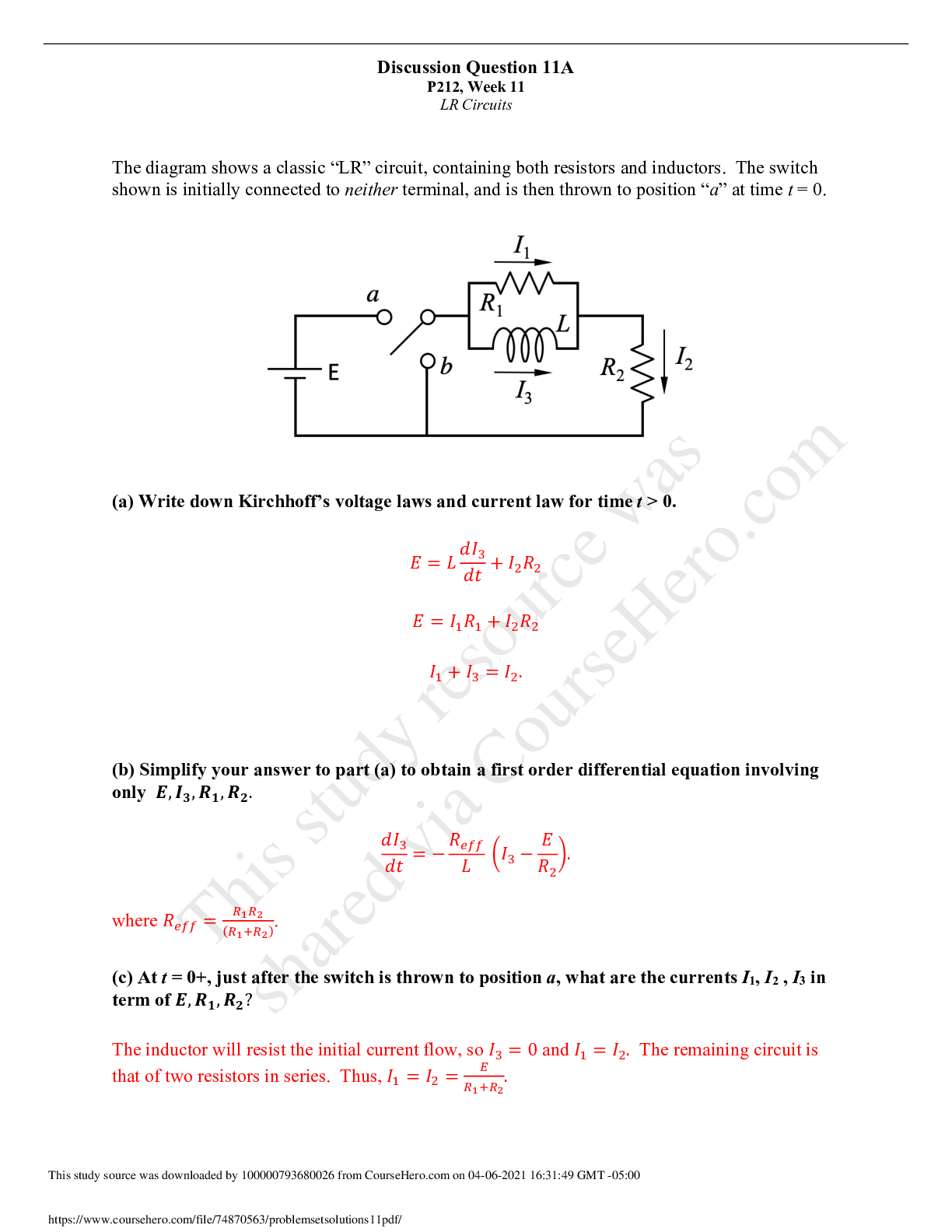
Discussion Question 11A P212, Week 11 LR Circuits The diagram shows a classic “LR” circuit, containing both resistors and inductors. The switch shown is initially connected to neither terminal... , and is then thrown to position “a” at time t = 0. (a) Write down Kirchhoff’s voltage laws and current law for time t > 0. (b) Simplify your answer to part (a) to obtain a first order differential equation involving only *, ,$, -%, -&. $%! $& = - (c) At t = 0+, just after the switch is thrown to position a, what are the currents I1, I2 , I3 in term of *, -%, -&? The inductor will . (d) Using the initial conditions found in part (c), solve the differential equation in part (b) for ,$(5). Solving for %!(&) in part (b), we get %!(&) = !(" + 7 8. )#$$ / 0 where 7 is the integration constant. Imposing the condition %!(0) = 0, we get %!(&) = - )" (1 - 8. %#$$ & 0) Next, after a very long time, the 'clock' is reset to 0 and the switch is thrown to position b. (e) Write down the new Kirchhoff’s voltage law and solve the current through the inductor as a function of time. The resulting circuit is a series RL circuit with resistance ('(( = ())!!+))""). The KVL equation is thus . The initial current %1 is obtained from part (d) to be - )" . Hence, %!(&) = !(" 8 . )#$$ / 0 [Show More]
Last updated: 1 year ago
Preview 1 out of 7 pages
Reviews( 0 )
Document information
Connected school, study & course
About the document
Uploaded On
Apr 07, 2021
Number of pages
7
Written in

Additional information
This document has been written for:
Uploaded
Apr 07, 2021
Downloads
0
Views
49


.png)


.png)
.png)